|
光学测试平台光学测试平台 Optical Shop Testing Set-ups 原文:Flexible Optical B.V., The Netherlands(OKO Tech) 翻译:灵动智能光学,152 5716 7514 ,info@inspiroptics.com
Optical setup for testing of optical components with the Shack-Hartmann wavefront sensor should satisfy the following conditions: 利用Shack-Hartmann波前传感器测试光学元件的光学装置应满足下列条件: The relay optics should re-image the plane of the object to the plane of the Hartmann mask (lenslet array). 该接力光学系统应将物面重新成像到哈特曼掩模平面(透镜阵列)。 The scheme should scale the beam is such a way that the image of the scaled object (wavefront) is densely filled with Hartmann sub-apertures. 该光路系统应缩放光束,使缩放对象(波前)的图像充满哈特曼子孔径。 The optics should allow for calibration. In the general case, it consists of separate measurement of the complete setup aberration with ideal object or a source of ideal wavefront,replacing the one to be tested. 该光学系统应允许校准。通常情况下,他应该可以利用理想物体或理想波前源单独测量整个装置的像差,然后再测量待测像差。 下面考虑三种典型的测量方案。 1. Testing of transmission optics (透射光学器件测试)
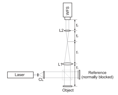
图 1. Shark-Hartmann波前传感器测试透明光学器件的典型测量方案 (CL:准直器;L1和L2:焦距分别为f1和f2的透镜;WFS:波前传感器) Typical measurement scheme for testing of transparent optics with Shack- Hartmann wavefront sensor. Here CL is a collimator; L1 and L2 are lenses with focal distances f1 and f2, respectively; WFS is the wavefront sensor.
A typical optical optics setup for measurement of transparent optics with Shack-Hartmann wavefront sensor is shown on Figure 1. The object under test should be placed in a collimated laser beam. A telescopic system consisting of two lenses,L1 and L2,is used to re-image the aperture of the object to the microlens array(or Hartmann mask)of the wavefront sensor. The system should scale the area to be measured to the aperture size of the wavefront sensor;the scaling factor is equal tof1/f2,where f1and f2 are focal distances of the lenses L1 and L2,respectively. 用Shark-Hartmann波前传感器测量透明光学器件的典型光学装置如图1所示。被测量物体应置于准直激光束中。由L1和L2两个透镜组成的望远镜系统用于将物体的孔径重新成像到波前传感器的微透镜阵列(或哈特曼掩模)上。系统应根据波前传感器的孔径大小缩放待测区域。缩放系数等于f1/f2,其中f1和f2分别是透镜L1和L2的焦距。 Although ”FrontSurfer” is able to perform “absolute” wavefront measurement without any reference pattern, it is advisable to switch to the reference mode. It allows to get rid of aberrations of the relay optics, which are always present due to imperfection of the components and misalignment in the system. Reference pattern can be measured with the object removed from the setup. 尽管“FrontSurfer”软件能都在没有任何参考模式的情况下进行“绝对”波前测量,但还是建议切换到参考模式。它可以消除由于元件的缺陷和光路未完成对准而导致的光学系统像差。在测量参考图像时,被测物体应从光路中移除。 2. Testing of reflective optics (反射光学器件测试) A typical optics setup for measurement of reflective optics is shown on Figure 2. To facilitate calibration, it is convenient to build it in a similar way to the Twyman-Green interferometer, where a beam splitter divides the incoming beam in two branches. The object is placed the in first branch behind the beam splitter, and the reference (normally a high-quality flat or spherical mirror) in the second one. The beams reflected from the object and reference are them directed to the wavefront sensor. A telescopic system similar to the one from the previous scheme (Figure 1) is used to provide conjugation between the object and WFS with proper scaling. One of the branches should always be block-the first branch for measurement of the reference pattern, and the second one for testing of the object. 反射光学测量的典型光学装置如图2所示。为了便于校准,可以搭建类似于Twyman-Green干涉仪的光路,利用分束器将入射光束分成两个分支。物体放置在分束器后面的第一个分支中,参照物(通常是高质量的平面镜或球面镜)放置在第二个分支中。从物体和参照物反射的光束入射到波前传感器中。可通过一个类似于上一个方案(图1)的伸缩系统来实现物体和WFS之间的共轭,以及适当的缩放。第一个分支用于测量参考模式,第二个分支用于测量待测对象。
图 2. 利用Shack-Hartmann波前传感器测试反射光学器件的测量方案(符号参见图1) Typical measurement scheme for testing of reflective optics with Shack-Hartmann wavefront sensor. See Figure 1 for notations. 3. Testing of micro lenses (微透镜测试)
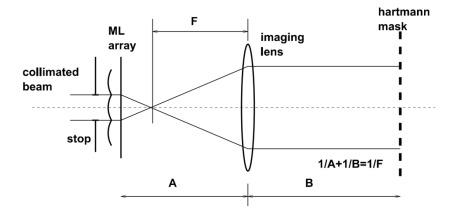
图 3. 用Shack-Hartmann波前传感器测试微透镜的测量方案 Measurement scheme for testing of a microlens with Shack-Hartmann wavefront sensor.
An example of a relay system designed to measure the aberrations of a microlens for fiber coupling applications is shown in Figure 3. In this case the microlens has a small diameter (1 mm) compared to the Hartmann mask aperture (4 mm). A telescope formed by the microlens itself and the imaging lens is used to couple the microlens aperture to the sensor mask.The Hartmann mask is co-incident with the microlens image. 图3是一个光学系统的例子,该系统用于测量光纤耦合应用中微透镜的像差。在这种情况下,与哈特曼掩模孔径(4 mm)相比,微透镜的直径较小(1 mm)。由微透镜本身和成像透镜所形成的望远镜用于将微透镜孔径耦合到传感器掩模。哈特曼掩模与微透镜图像处于同一位置。 Calibration of the setup consists of two steps: 校准包括两个步骤: (1) Obtaining of an ideal reference. 获得理想的波前参考。 (2) Calibration of the imaging microlens. 校准成像微透镜。
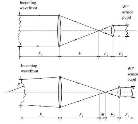
In the first step we ensure that the aberration of the illuminating beam is negligible over the aperture of the microlens. In the simplest case this can be achieved by illumination of the microlens with slightly divergent wavefront produced by a remote pinhole source. If there are no optical components between the pinhole and tested microlens, we can be sure the illumination wavefront is close to ideal. 在第一步中,我们确保在微透镜的光圈上照明光束的像差可以忽略不计。在最简单的情况下,这可以通过用远程针孔源产生的略微发散的波前照明微透镜来实现。如果针孔与被测微透镜之间没有光学元件,则可以确定照明波前接近理想。 In the second step, we place another pinhole in the focus of the microlens. By doing that we eliminate all aberration of the setup, except for the aberrations introduced by the imaging lens,to be able to measure the aberration of the relay optics only. 在第二步中,我们在微透镜的焦点上放置另一个针孔。这样可以消除成像透镜像差之外的所有像差,以便能够只测量接力光学元件的像差。 In the last step, we remove the pinhole and measure the total aberration. To obtain the aberration of the microlens, the aberration of the imaging setup measured at step 2 should be extracted from the measurement result. 最后,我们去除针孔并测量总像差。为了获得微透镜的像差,应该从测量结果中去掉在第二步测量的成像装置的像差。 In this example we have used slightly divergent wavefront instead of collimated. This does not introduce any significant problem if the radius of curvature of wavefront is much larger than the focal length of the microlens under test. If the lens has focal length of 4mm and point source is placed at 1m from the lens, spherical aberration introduced by“wrong”illumination is negligible. Nevertheless, it is always advisable to check expected aberrations using ray-tracing code. 在这个例子中,我们使用了略微发散的波前而不是准直的波前。如果波前的曲率半径远大于被测微透镜阵列的焦距,则不会出现问题。如果透镜的焦距为4 mm,并且点光源距透镜1米,那么由“错误”照明引起的球差可以忽略不计。无论如何,我们还是建议使用光线跟踪代码来检查期望的像差。 4. Optical conjugation 光学共轭 The input pupil of the WF sensor should be optically conjugated with the pupil of the optical system. Conjugated is achieved by placing the sensor input in the image of the pupil. If the sensor is positioned outsider of the pupil image, any aberrations in the pupil will cause geometrical beam distortions in the sensor input, important: wrong conjugation is the cause of numerous disappointments with WF measurement. 通过将波前传感器放置于光学系统入瞳的图像位置,实现传感器的输入光瞳与光学系统入瞳的光学共轭。如果传感器位于瞳孔图像之外,则入瞳中的任何像差都会导致传感器输入中的几何光束畸变,从而导致测量错误。因此,入瞳共轭非常重要:共轭错误会使波前测量的结果不尽人意。 Usually the conjugation is achieved with an afocal telescope, formed by two positive lenses with focal lengths F1 and F2,respectively. 通常共轭是通过无焦望远镜实现的,无焦望远镜由两个焦距分别是F1和F2的正透镜组成。 The coupling telescope reduces the transversal dimension of the light beam by a factor(F1/F2), and magnifies all ray angles with the same factor, thus preserving the geometrical of aberration ∆ . For the input aberration represented by a parabola ∆(a)=a2/2R where a is the radial coordinate and R is the radius of curvature, the F number FN is defined as R/A, where A is the semi-diameter of the input pupil. Expressing the F number in terms of aberration amplitude, we obtain FN=A/(2∆). If the aperture is reduced M times by the coupling telescope, the F number of the beam is also reduced M times. 耦合望远镜将光束的横向尺寸减小一个因子(F1/F2),并以相同的因子放大所有光线角度,从而保持像差的几何振幅∆。对于以抛物线∆(a)=a2/2R表示的输入像差,其中a是径向坐标,R是曲率半径,F数FN定义为R/A,其中A是输入光瞳的半径。用像差振幅表示F数,得到FN=A/(2∆)。如果耦合望远镜使孔径减小M倍,光束的F数也减小M倍。 Scaling of the F number imposes serious practical restrictions on the range of optical powers that can be controlled by the sensor. The practically acceptable range of F numbers is always limited by the complexity and aberrations of the telescope optics While F numbers in the range between infinity and 10 are easily achievable with single lenses and achromatic doublets, the range between 10 and 3 calls for a somewhat mere complicated optics and, finally, the range between 3 and 1 can be very expensive and also very difficult to correct for intrinsic aberrations. F数的缩放对可由传感器控制的光功率范围施加了严重的实际限制。实际可接受的F数范围总是受到望远镜光学系统的复杂性和像差的限制。虽然使用单透镜和消色差双透镜很容易获得无穷大到10之间的F值,但10到3之间的范围需要更复杂的光学系统;最后,3到1之间的范围可能非常昂贵,而且很难校正固有像差。 It follows from Fig. 4 that the F number of the wavefront at the telescope input should be considerably smaller than (FN/M) where FN is the F number of any of two lenses forming the coupling telescope-assuming that both components of the telescope have equal F number - and M is the telescope magnification. Finally, both the wavefront curvature and the wavefront tilts should not exceed the specifications of the sensor at the input pupil of the sensor. 从图4可以看出,望远镜输入处波前的F数应明显小于(FN/M),其中FN是构成耦合望远镜的两个透镜中任意一个透镜的F数(假设望远镜的两个组件具有相等的F数),M是望远镜的放大倍数。最后,在传感器的输入光瞳处,波前曲率和波前倾斜都不应超过传感器的规格。
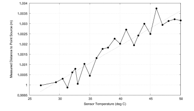
图 4. 零曲率的无焦望远镜中WF的缩放(上),以及非零曲率的补偿(下)。其中 Scaling of the WF in an afocal telescope with zero WF curvature(top),and compensation for a non-zero curvature (bottom).Here 4.1. Compensation of the curvature 曲率补偿 To secure the maximum measurement range for higher-order aberrations, the input of wavefront sensor have zero spherical term. To compensate for the sphericity of incoming wavefront, a calibrated spherical or parabolic phase shift could be added to the wavefront at the input of the telescope. This can be achieved by using a pinhole as a source of diverging in the diffraction angle 1/FN.To satisfy this condition, dp should satisfy to dp-FN*2.44 λ. 为了保证高阶像差的最大测量范围,波前传感器的输入应该具有零球面项。为了补偿入射波前的球形度,可以在望远镜的输入端对波前加一个校准的球面或抛物线相移。这可以通过使用针孔作为发散球面波的源来实现。针孔直径dp应产生衍射角为1/FN光束发散角。为了满足这个条件,dp应该满足dp-FN*2.44 λ。 Also, the WF curvature in the input pupil of the sensor can be compensated by changing the distance between the lenses of the telescope, preserving the position of the input pupil in the front focus of the first lens, and keeping the point of ray convergence in the front focus of the second lens. Under these conditions, the shift of the first lens is given by 此外,传感器的输入光瞳中的WF曲率可以通过改变望远镜的透镜之间的距离来补偿,保持输入光瞳在第一透镜的前焦点中的位置,并且保持光线会聚点在第二透镜的前焦点中。在这些条件下,第一个透镜的位移由 The easiest practical way to achieve such a compensation consists the wavefront sensor, together with the second lens of the telescope, on a moving stage with movement range of at least 实现这种补偿的最简单实用的方法是将波前传感器与望远镜的第二个透镜一起安装在望远镜上移动范围至少为 4.2. Thermal stability consideration 有关热稳定性的考虑 Some camera models, particularly those with higher maximum frame rate are known to product appreciable amount of heat. Due to thermal expansion the size of the image sensor changes with the temperature increase. Thus, pixel pitch either nominal or measured during calibration might not be accurate anymore. To illustrate the Fig. 5 (top) shows typical aberration introduced by thermal expansion after changing the temperature of CMV4000 imaging chip from 30℃ to 50℃. As can be predicted main aberration type is defocus, it is measured about one order of magnitude higher than others. The measured error of radius of curvature relates linearly to the temperature of wavefront measurements, especially in absolute mode the is advised to keep the temperature of the camera as constant as possible. 某些相机,特别是帧率高的相机,在工作过程中会产生大量的热量。图像传感器尺寸会由于热膨胀随着温度的升高而变化。因此,正常的或校准期间测量的像素间距可能不在准确。为了说明这种效果,图5(上)显示了将CMV4000成像芯片的温度从30 ℃改变到50 ℃后,热膨胀引起的典型像差。可以预测,主要像差类型为离焦,测量值比其他像差高出一个数量级。曲率半径的测量误差与温度呈线性关系,如图5(下)所示。为了达到波前测量的最终精度和可重复性,特别是在绝对模式下,建议用户尽可能保持相机的温度恒定。
图 5. 图像传感器热膨胀对波前测量的影响。上:由于CMOS传感器温度从30 ℃改变到 50 ℃而引起的假散焦;下:观察到的点源距离随着图像传感器温度的变化而变化。 Effect of image sensor thermal expansion on wavefront measurement. Top: spurious defocus caused by increase of the CMOS sensor temperature from 30℃ to 50℃. Bottom: observed change in distance to a point source with the change of the image sensor temperature.
上一篇产品应用以及国际最新进展下一篇自适应光学系统设计 |